Reflow Oven
Contents
Introduction
Reflow oven is a tool for fast automated soldering of SMT components on PCB.
Cheapo variant could be made from old toaster since it's internals are de-facto all we need - oven with heating element! We strip it off original electronics and mechanics (such as springs) first. We're going to solder, not toast! Now we can't even turn it on, so we'll add some sort of regulator, temperature sensor and logic.
Description
Regulation
Our toster draws 860W of AC power. That makes for ~3.74A at 230V.
I've decided to go after semiconductors instead of relays. It promises much higher lifetime and very fine control of delivered power.
Triac of choice was BT136-600, rated for 600V and 4A which eventually should be enough. For safety reasons the triac will be triggered by MOC3020 optotriac. The power circuit is placed on separate hand-drawn PCB, with two connections - hot, load for 230V and gnd, +5V for control. Power itself is regulated by waiting for mains power to cross zero as this is a start of a new 20ms cycle (50Hz). Then we'll wait some time between 0 - 20ms and send a trigger pulse. This causes optotriac to open and let current flow across main triac gate and open it until new cycle begins.
Zero crossing is sensed by external interrupt pin on ATMega48 driven by transistor connected to rectifier diode bridge. The rest of circuit is powered through one more diode, so that it could be filtered and stabilized. Whole circuit is powered by 230-12V transformer.
There was a bug found in PCB creation software for triac package, so that board worked after second iteration which is featuring BT138-800 instead (12A, 800V).
Temperature
PT100 has been chosen for it's high thermal range and very good precision. That unfortunately means that readout will be a bit more involved.
PT100 itself will be read out using a 4-wire-method. It will be placed between two 50k resistors. That limits current to approximately 50 micro amperes at 5V supply and it won't undergo any self heating due to high current. PT100's resistance change with temperature, so does voltage across it which is exactly what we're about to measure. Each side of PT100 is connected using 2k resistors to a buffer amplifier whose output is then fed to difference amplifier with appropriately tuned gain. Output is then buffered / amplified once more. This is finally connected to LTC2450 16-bit ADC providing us with SPI interface and allowing for about 0.015 Ohm resolution or about 0.024 deg. C (~14bits).
User Interface
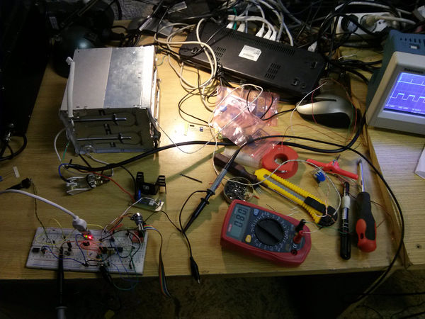
Oven is currently in mark zero phase. It is a prototype lacking temperature sensing. Ordinary potentiometer connected to mega's ADC is used to directly set trigger delay (and hence output power). Board writes debug information on USART.
Plan is to have one mega taking care of regulation itself while listening on USART for commands, which can be conveniently sent from anywhere. Such as second MCU taking care of user interaction only - drawing on display, waiting for user input. Regulation can be distributed this way across both mcu's. Leaving regulation mcu program very simple - only with PID, ramping, temperature (over SPI) and USART. With actual "baking recipes" implemented in ui mcu (then replayed as commands for reg. mcu).
Casing
Idea is to cut some wood pieces and use them. Oven itself is made of metal, so perhaps 4 cm spacer columns would be good enough for wood not getting too hot.
Status

Current prototype shows that oven can get very hot very rapidly (~400C in 30sec.) so that fine regulation is truely needed.
Tesing runs
- 10th June 2014
I did some pictures - setup, populated board, board in the oven, and soldered result. The board was over lit by UV and then etched way too much. We didn't care and used it even if it wasn't going to work.
Done
- Power switching part on PCB with improvised connection to oven
- MCU is still on breadboard.
Missing
- temperature readout
- mcu board
- casing design
- ux design
- ramping functionality in regulator


